Building the IsoBevel™ Grinder/Sharpener Prototype "DOMAN MARK I"
Since the IsoBevel™ is not currently licensed and is not in production, the only way to own one is to build it yourself. I designed and built the Mk. 1 for my own use because I thought popular commercial wet wheel sharpeners were overpriced and did not offer a fast and convenient means of providing the user with bevel angle control. The Mk. 1 was designed to overcome the shortcomings of these commercial sharpeners. At the time, I was not worried about design for mass production, I just wanted to create the best hollow grinding machine possible.
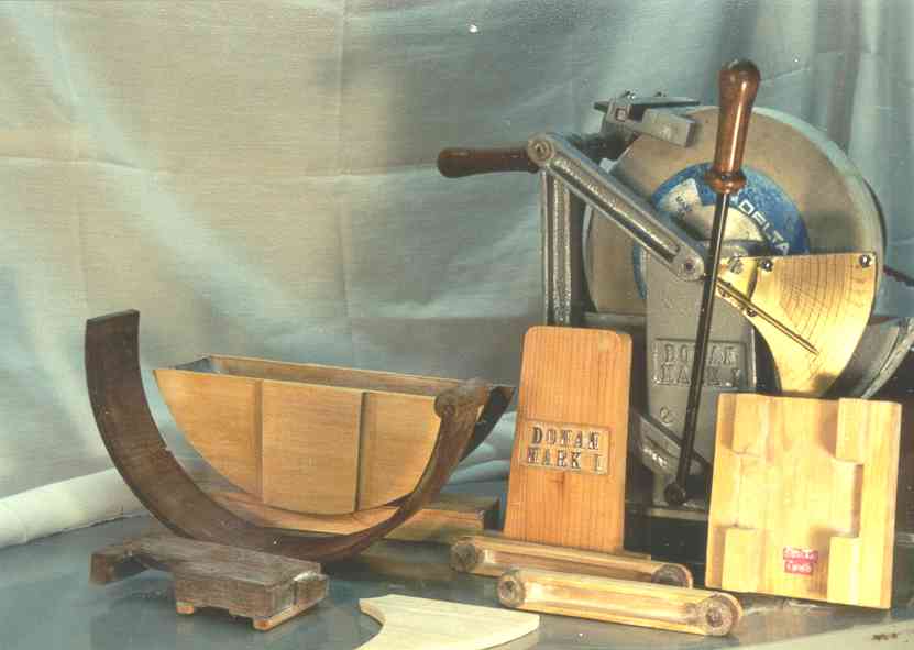
The Mk. 1 was built using the metalcasting techniques that I learned when building the Gingery Lathe and Milling Machine. The lathe and milling machine were also used in the construction of the Mk. 1. All of the Mk 1. metal casting patterns were all straightforward to build, with the exception of the sliding ring patterns used for the bottom of the water pan and tongue. The metalcasting patterns and the finished grinder are shown in the picture below.
The picture below shows all of the Mk. 1 parts organized for assembly.
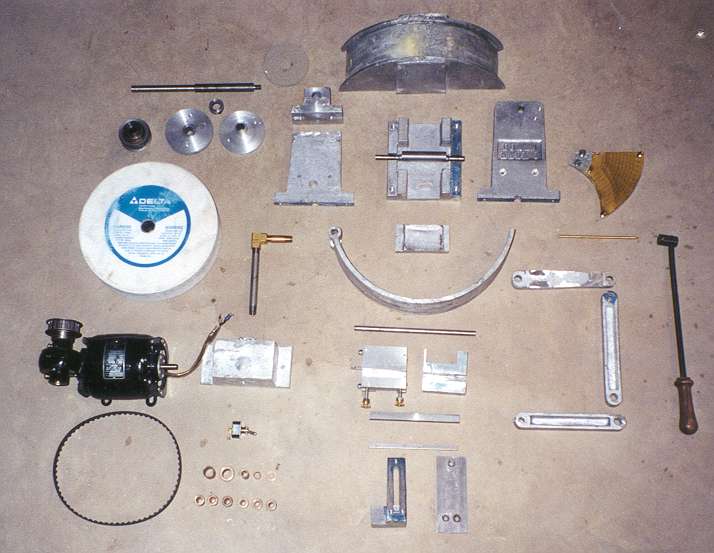
Parts (Left to Right roughly):
Bodine 90 RPM Worm Gear Motor with Cogbelt Pulleys
Cogbelt
Bronze Bushings for 3/8" for linkage parts and clamping cam, 3/4" for arbor.
Switch and switchbox (Used Gingery Lathe bed support pattern)
10" grinding wheel for a Delta 23-700 wet/dry sharpener
Arbor (turned on Gingery Lathe, threaded on one end with die)
Large washers/bushings and cardboard spacer for securing grinding wheel to arbor
Pillow block for arbor
Arbor support with hole for drain pipe.
Drain pipe (Valve not shown, allows easy waterpan cleanout)
Waterpan (Bottom of pan has cylindrical profile to match sliding ring)
Base
Cam (eccentric turned on 2 sets of centers on Gingery Lathe)
Cam clamping pad (cam moves pad up and down to secure sliding ring (tongue against matching waterpan bottom.)
Sliding Ring with integrated toolrest pin support
Toolrest (Optional detachable end, groove for optional tool guide, note: recommend solid toolrest)
Tool guide (fits in groove)
Cold-rolled steel ways
Toolrest ways support
Linkage support casting (pattern lettering from plastic clock letter number set)
IsoBevel scale (etched brass scale)
Scale support casting (attaches to linkage support casting)
Brass pointer
Parallelogram linkage members
Cam clamp handle
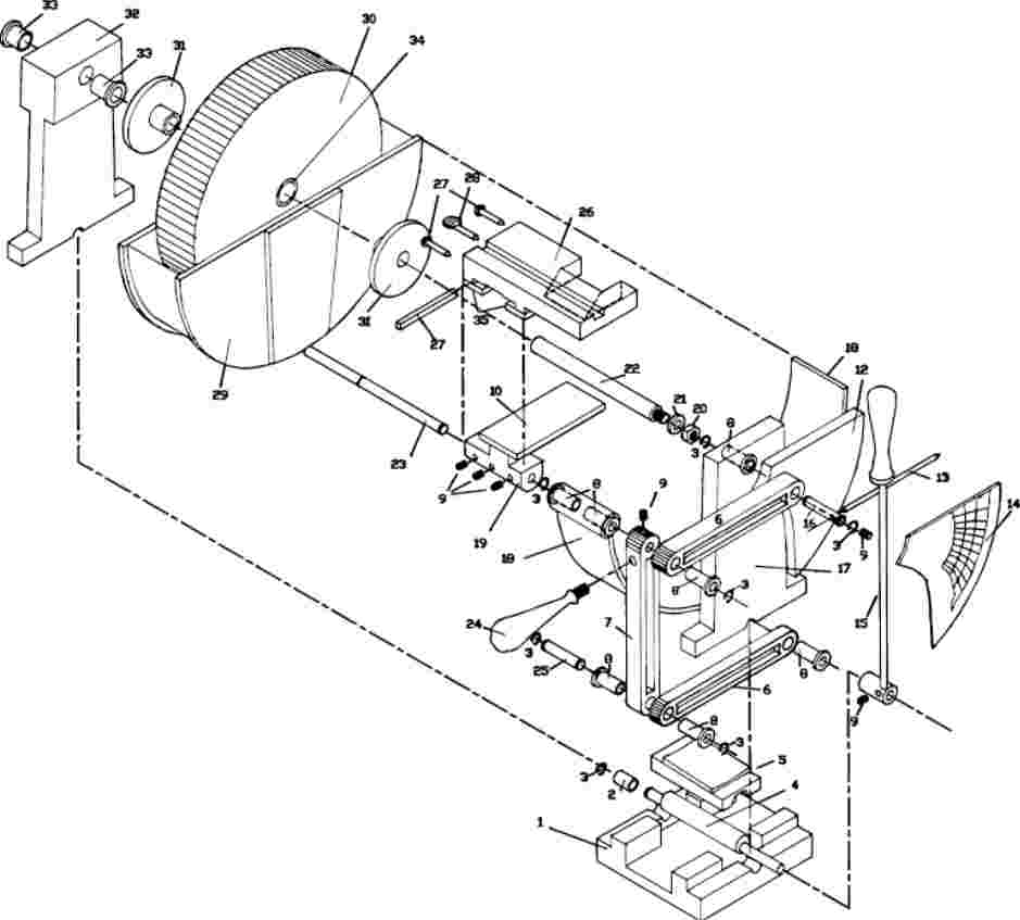
Putting it All Together
The drawing below, shows how the parts all fit together. Part identification can be found in U.S. Patent 6,381,862.
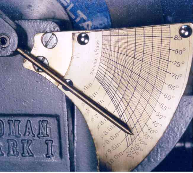
Making the Scale.
The IsoBevel scale was another piece of the Mk. 1 that was difficult to make. Click the links for background on the mathematics and software that can be used to make the scale. After generating a scale in .dxf format, it can be read into most any CAD package. CAD packages can generate HPGL files for XY plotters. I have a Houston Instrument ImageMaker that is a flatbed plotter. First, I turned a steel pen that had the same dimensions as the plastic pens that my plotter used. I ground a scribe from an 1/8" HSS drill bit that fit in the steel pen that I turned for the plotter. Next I coated a piece of brass with shellac and secured it to the bed of the plotter. I then plotted the file as usual. The scribe scraped fine lines into the shellac which exposed the bare brass below. Plotting the file twice does not hurt. Next, I removed the brass plate from the plotter and placed it in etching solution made for printed circuit boards (PCB etchant solution from Radio Shack (ferric chloride)). After about 10 or 15 minutes, depending on temperature and how deep you want your lines, you can remove the plate from the solution and thoroughly rinse the plate. You are not done just yet. In order to chemically blacken the lines for improved visibility, rub gun blue solution over the plate and the lines will turn black. Rinse thoroughly. You can now sand the shellac from the plate with 400-600 grit sandpaper on a block to obtain a brushed brass look. The black lines will remain. Polishing and buffing tends to remove the black from the lines, so I recommend sticking with a brushed look. Take the recommended precautions when working with the chemicals, i.e. chemical resistant gloves, safety glasses or shield, respirator, etc. There are certainly many other options to consider, laser engraving, CNC engraving, photo-etching etc. The method described above was used simply because it fit within the capabilities of the equipment that I owned at the time.
Construction Notes
Under Construction..
Mathematics of the IsoBevel™ System
Copyright © 2003 David B. Doman, PhD All rights reserved.