Certain geometric parameters must be specified in order to
generate a scale. These parameters may be specified by pulling-down the Design menu and
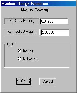
selecting Specify Machine Geometry.
First specify R, the length of the upper and lower
cranks. Note that R must be greater than the maximum grinding
wheel radius. Next specify dy
which is the perpendicular distance between the tool support plane and
the center of the red pivot pin or toolrest support pin.
As a practical matter, dy should be equal to the height of
the centerline of the average blade to be ground on the machine.
For example if the tool support plane was 1 7/8 inches from the red pivot
pin, and a typical blade was ¼ in thick, the distance dy should
be set to 2 inches (i.e. 1 7/8 “ + ¼ “ x ½
= 2” ). This is not critical as long as the radius of the grinding
wheel is large when compared to the thickness of the blade. Be sure to enter dy and R in
consistent units. You may select
inches or millimeters using the radio buttons in the Specify
Machine Geometry dialog box.
It should be noted that the coupler bar, toolrest support
pin, and tool support plane are rigidly coupled together and move as a unit.
Also note that these parts maintain a fixed angular orientation with
respect to the ground plane as the cranks and pointer rotate.
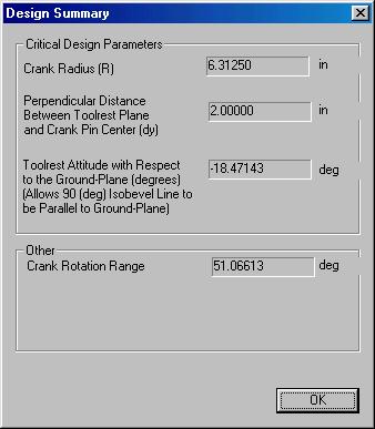
The Design Summary dialog
box echoes the crank lengths R and dy.
It also conveys the tool plane inclination angle with respect to
the ground plane required for the 90 degree IsoBevel contour line to be parallel
to the ground plane. The 90 degree
contour will always be a straight line and it is desirable to have this line as
well as the crank links and pointer parallel to the ground plane for this
special case. The Design Summary indicates how much the tool support
plane must be inclined to the horizontal ground plane in order to achieve a 90
degree bevel angle under this condition. The
Crank Rotation Range specifies the angular range of travel that the
linkage must pass through in order to obtain a range of bevel angles between 0
and 90 degrees for a grinding wheel of maximum radius (see Scale Settings). This range will always be less than 90 degrees and should
preferably be less than 60 degrees to maintain favorable transmission angles.
Regenerate Scale causes the scale in the window to
be redrawn. A typical scale in a
window is shown below.
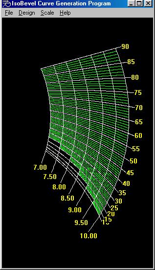
Keep
in mind that the scale in the window may not be displayed with the proper aspect
ratio. DXF and XYZ files will have
the correct information so a CAD program can print to scale.
The scale settings allow one to customize a scale by
setting the tick lengths, range of grinding wheel sizes that the scale
accommodates and number of grinding wheel arcs to draw on the scale.
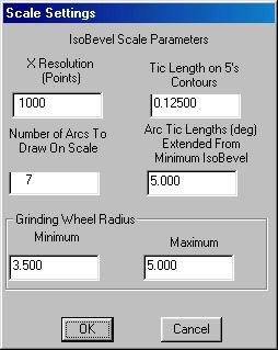
The X Resolution (points) defines the number of
points between the grinding wheel center and the maximum grinding wheel
radius at which to calculate the each point on each contour line.
The higher the resolution the more accurate and smooth the IsoBevel
curves will be. Higher resolutions
require longer computation times and result in larger .DXF files. The Tic Length on 5’s Contours define how far every
5th contour line extends beyond the largest arc on the scale.
This distance must be expressed in units (inches or millimeters) that are
consistent with the design parameters specified under the Design menu.
Number of Arcs to Draw on Scale specifies how many grinding wheel
radius arcs are to be drawn on the scale. Arc
Tic Lengths specify the how many degrees below the lowest IsoBevel contour
each grinding wheel radius arc should extend.
The range of grinding wheel radii that the scale will accommodate is
specified by entering the Minimum and Maximum grinding wheel
radii.
The Minor Contours dialog box controls the lengths
of groups of contour lines between each 5 degree increment (i.e. the green
curves in the scale). Because the
distance between the contour lines decreases as the bevel angle decreases, the
lines on the scale can become very close together making the scale difficult to
read. The Minor Contours dialog box allows the user to specify the radial
range over which each group of minor contours is drawn.
The settings for the scale shown above are as follows:
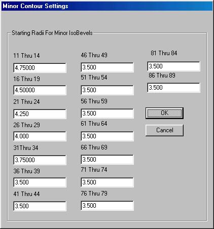
Note that contour lines 11 through 14 start at a radius of
4.75 inches and end at a radius of 5 inches (maximum grinding wheel radius),
The 16 through 19 degree IsoBevel contours start at a radius of 4.5
inches and extend to 5 inches. In
summary, the upper bound is assumed to be equal to the maximum grinding wheel
radius while the lower bound for each set of minor contours is adjustable.
Open Design : Open
a design file. A design file stores
all scale parameters.
Save Design: Saves
the current design information and scale parameters necessary to regenerate the
scale.
Export .DXF: Saves
the current scale in DXF Drawing Exchange Format so that it can be imported
into nearly any CAD package. The
indicia are stored as text and their position may be modified using the CAD
package for an aesthetically pleasing scale.
The scale can be printed “to scale” from the CAD package.
Export .XYZ: Saves
the current scale data by writing the x-y coordinates of each point on each
contour line on a line of an ASCII text file.
The (x,y) data for each contour line is separated by a blank line.
No text labels are stored. This
format is can be imported into some CAD packages and can be read by nearly all
graphing and plotting packages.
Exit: Exit the program
Back
Home
Contact