Compound Miter Calculators for Use in the Shop
Below you will find links to PDF files that you can print to make your own compound miter slide rules. They are free to download for your personal use. If you are interested in commercially producing these devices please contact me to discuss licensing.
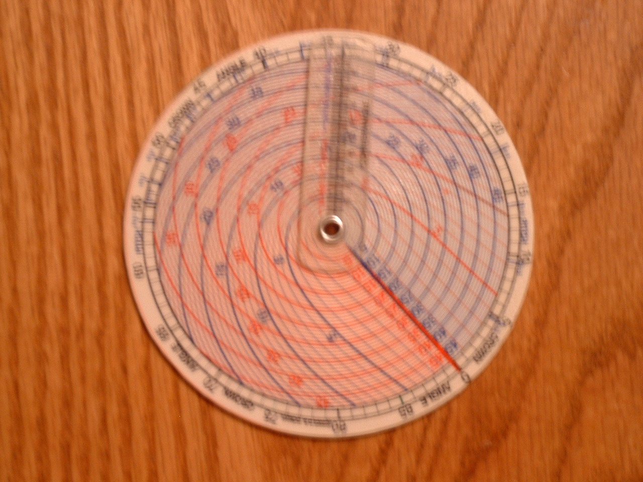
Type I Slide Rule
Type I Compound Miter Slide Rule in PDF Format
Instructions for making the Type 1 Slide Rule.
Print out 2 copies of the PDF file on cardstock. First cut out the two discs printed on the page including the numbers on the outer rings. Use rubber cement to glue the two discs back-to-back. The orientation of the disks is not important. Next cut out the inner disks by trimming off the lines and numbers associated with the outer ring. As an option, you can print a 3rd copy on a transparency and cut out the arrows at the bottom of the page which can be pinned or riveted to the center of the disks to help you read solutions to the compound miter problems that you encounter. Use a pin or rivet to hold the stack of disks (and arrows if used) together making sure that the Side A inner disk is placed on the Side A outer disk and that the Side B inner disk is place on the Side B outer disk. Optionally you can glue the disks to a CD for a sturdier backing; however you will need to fill the center hole with something solid. I also used a piece of acrylic plastic as a backing for the transparency using rubber cement a the adhesive.
Overview
The whiz-wheel can be used to calculate miter saw, table saw, or radial arm saw angle settings required to cut crown molding, roof stringers or panels for hips and valleys. The wheel allows one to calculate and set-up a saw in the shop with resorting to searching through pages of compound miter tables or resorting to computer programs. The wheel is set-up to handle crown molding angles from 0-60 deg or slopes from .176 - 1.73 and flat-miter angles from 10-60 deg. It also has a scale that allows one to convert slope measurements to crown angles and a table that lists flat-miter angles for closed polygons with 3 to 10 sides. In addition, the compound miter formulas are printed on the wheel to allow the user to calculate saw settings for flat-miters and crown-angles in the unusual event that one must solve a problem outside of the range that can be handled by the wheel.
Definitions:
Flat Miter – The angle that you would cut to join two flat boards in order to bend them around a corner. (Flat Miter = ½ x Angle of Bend)
Crown Angle – The angle that the crown molding makes with a line parallel to the ceiling or the ground (i.e. local horizontal).
Miter – The miter angle that you set on your miter gage or miter saw box.
Bevel – The tilt angle that you set on your saw. (i.e. the tilt angle of the blade measured from vertical)
Cursor – The blue line and arrowhead on the clear plastic spinners.
The wheel has two sides. Side A is used to compute the saw miter angle given the flat miter angle and crown angle, while Side B is used to compute the saw bevel or tilt angle given the flat miter and crown angle.
The instructions are provided on the wheel; however, they are repeated here for convenience.
SIDE A: Miter calculation instructions
1. Align red arrow on inner wheel with flat-miter angle on outer scale
2. Move blue arrow over the crown angle on inner wheel
3. Read saw miter setting at blue arrow tip on outer scale
SIDE B: Bevel (saw tilt) calculation instructions
1. Align red arrow on inner wheel with flat-miter angle on outer scale
2. Move blue arrow over the crown angle on the inner scale
3. Read bevel (saw tilt) angle setting at blue arrow tip on outer scale
Two different example problems are provided that take you through the process of computing the correct saw settings for different situations.
Example 1:
Crown Molding
Suppose that you are installing crown molding in a rectangular room and you need to determine how to set-up a compound miter saw to correctly cut the crown molding. The first step is to determine the crown-angle of the molding. Figure 1 shows the definition of the crown-angle and its relationship with the rise and run of the molding.

Figure 1. Crown Angle definition as shown on whiz-wheel.
A simple way to measure the RISE and RUN is to insert the molding into a framing square as shown in Figure 2. From Figure 2, we see that the RISE = 1 1/2” and the RUN = 1 5/32” (slightly larger than 1 1/8”) . The SLOPE = RISE/RUN or 1.5/1.156 = 1.297.
Figure 2. Crown molding inserted into framing square
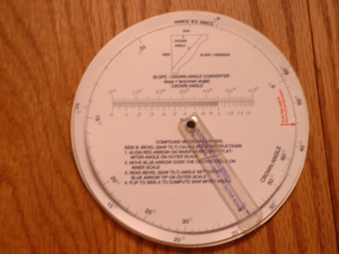
Now that the slope has been calculated, you can use the CROWN ANGLE – SLOPE CONVERTER scale on the whiz-wheel to find the crown angle from the slope. Figure 3 shows how to use the scale to convert the slope of 1.297 to a crown angle.
The slope of 1.297 is approximately located at the blue arrow which corresponds to approximately a 52.5 deg crown angle. (Tip: You can get greater accuracy for crown angles greater than 45 deg by computing RUN/RISE and finding the crown angle on the high resolution scale and subtracting the result from 90 deg. For example RUN/RISE = 0.77 which corresponds to an angle of 37.5 deg; 90 deg – 37.5 deg = 52.5 deg. Alternatively the crown angle can be calculated using a scientific calculator by computing arctan(SLOPE) = arctan(1.297) = 52.367.)
RESULT: CROWN ANGLE = 52.5 deg
Since rooms are rarely truly square, it is a good idea to measure the actual corner angles in the room. This could be accomplished with a bevel square and protractor or other angle measuring device. Suppose that we measure the angles in our room and find that the following situation exists:
Figure 4. Rectangular room example.
Ideally we would expect each angle to measure 90 deg; however, we find that the actual corner angles range from 87-93 deg. The flat miters are simply half the angles that we measured in the corners, which are the miter gage settings that we would use if we were cutting flat molding. We will do a sample calculation for the 89 deg corner. The flat miter for the 89 deg corner is 89/2 = 44.5 deg.
FLAT MITER = 44.5 deg.
Now that we have the FLAT MITER = 44.5 deg and CROWN ANGLE = 52.5 deg, we can use the whiz wheel to determine the saw settings. First we flip the wheel to SIDE A which we will use to find the saw miter angle. First we align the red arrow on the inner disk with the FLAT MITER angle of 44.5 deg. Next we rotate the transparent spinner with the blue arrow to the crown angle of 52.5 deg on the inner ring. Finally we read the value of the saw miter angle at the tip of the blue arrow on the outer ring which reads 30.8 deg.
Next we flip to SIDE B to which we will use to find the saw bevel or tilt angle. First we align the red arrow on the inner disk with the FLAT MITER angle of 44.5 deg. Next we rotate the transparent spinner with the blue arrow to the crown angle of 52.5 deg on the inner ring. Finally we read the value of the saw bevel angle at the tip of the blue arrow on the outer ring which reads 33.8 deg.
In summary, the saw bevel angle is 33.8 deg and the saw miter angle is 30.8 deg.
Example 2:
6 Sided Bird House Roof
Suppose that we wish to determine how to set-up a saw to cut the panels for an 6 sided bird house roof with a slope of 5/12. We first convert the slope to a decimal, 5/12 = .417 and use slope to crown angle converter scale on SIDE B of the whiz-wheel. From the scale we conclude that a slope of .417 corresponds to a crown angle of about 22.5 deg. From SIDE A, we use the table that provides the flat-miter angles that correspond to closed polygons with a specified number of sides. The flat-miter for a 6 sided figure is 30 deg. First we flip to SIDE A and align the red arrow with the flat-miter angle of 30 deg. Next we rotate the cursor to the crown angle of 22.5 deg and read the saw miter angle of 28 deg on the outer scale next to the tip of the blue arrow. We now flip to SIDE B and follow the same procedure and read a bevel or saw tilt angle of 11 deg.
Type II Slide Rule
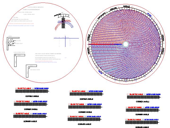
Type II Compound Miter Slide Rule in PDF Format
Instructions for making the Type II Slide Rule.
Print out 1 COLOR copy of the PDF file on cardstock. Cut out the disks and use rubber cement to glue them together back to back. Next print out another copy on a transparency. Cut out one of the rectangular bar scales at the bottom of the transparency sheet leaving some material extending beyond the "0" side of the "CORNER ANGLE" scale. Align the transparency such that the "0" line aligns with the innermost circle and the "100" line aligns with the boundary enclosing the colored curves. The tip of the arrow on the transparency should just touch the outermost ring that indicates the "CROWN ANGLE". When aligned tack or rivet the transparency to the center of the disk. Optionally you can glue the disks to a CD for a sturdier backing; however you will need to fill the center hole with something solid. I used a piece of acrylic plastic as a backing for the transparency using rubber cement a the adhesive.
Derivation of the Compound Miter Formulae
The compound miter formulae are well known; however, since I was unable to find the derivation of those formulae, my derivation is documented in the following PDF file.
Derivation of the Compound Miter Formulae in PDF Format
For those not interested in how they are derived, the final result is:
tan (saw miter) = tan(flat miter) cos(crown angle)
sin(saw bevel) = sin(flat miter) sin(crown angle)
Copyright © 2003-2007, David B. Doman PhD, All rights reserved.